Products - Electric Vehicle
FLEETWATCH Electric Vehicle Mileage, ID, Location, Data Capture Devices, & Charge Cord Management
Click on a product below for more information
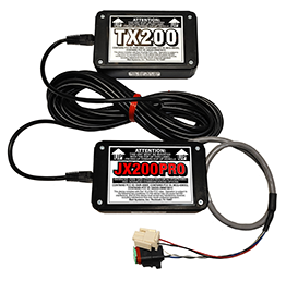
JX200 J1939 Data Logger Module
PRODUCT FEATURES
The FLEETWATCH® Model JX200 Data Recorder connects to an existing SAE J1939 connector on a vehicle. Data described below can be collected and reported on demand to a FLEETWATCH® RF Transceiver (TX200) for transmission to a wayside receiver station (FR200). The vehicle engine and transmission must have electronics necessary to output the requested information through the J1939/J1708 connector. The JX200 unit is user programmed with the vehicle number.
FAULT INDICATORS CAPTURED AND REPORTED
Fault Codes reported include Subsystem ID and Failure Mode Identifier as defined in SAE documentation. The JX200 reports the last 10 unique Active Fault Codes reported with the Date and Time of the beginning of the last occurrence observed. The JX200 can also look for specific fault codes and alert users at the next servicing if that code was recorded during the trip.
PROGRAMMING JX200 WITH VEHICLE ID
Vehicle ID can be programmed into the JX200 wirelessly using a Mobile Reader and Programmer. JX units may be programmed even while installed on a vehicle. The MR programmer is totally self contained and does not require a laptop or other PC to read or program the JX200 or other units.
INTEGRATED WITH FLUID MANAGEMENT SYSTEM
The JX200 Data Logger, integrated with the FLEETWATCH® Fluid Management System, allows automatic collection of vehicle number, life-to-date mileage, state of charge, as well as vehicle fault codes and other data obtained through the J1939/J1708 interface.
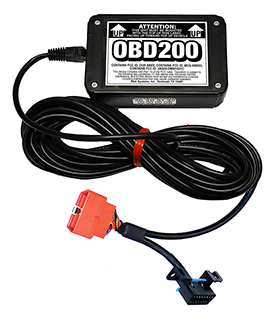
OBD200 Mileage and Data Logger Module
PRODUCT FEATURES
The OBD200 Mileage Tracking Module automatically counts and records miles traveled via a vehicle's existing OBD-II diagnostic port.
FAULT INDICATORS CAPTURED AND REPORTED
Fault Codes reported include Subsystem ID and Failure Mode Identifier as defined in SAE documentation. The JX200 reports the last 10 unique Active Fault Codes reported with the Date and Time of the beginning of the last occurrence observed. The JX200 can also look for specific fault codes and alert users at the next servicing if that code was recorded during the trip.
When the OBD200 receives a beacon signal from a receiving unit (see RECEIVER OPTIONS), it transmits the preprogrammed vehicle number, the life-to-date mileage of the vehicle, and coded data, including information on the status of the battery powering the unit, to the receiver. The data collected can be downloaded directly to an output device to generate mileage reports, or it can be combined with data collected from other FLEETWATCH® devices (see INTEGRATION WITH FLEETWATCH® FLUID MANAGEMENT SYSTEM) allowing completely automatic collection of vehicle number, life-to-date mileage, and state of charge.
Fleetwatch Cord Management System
PRODUCT FEATURES
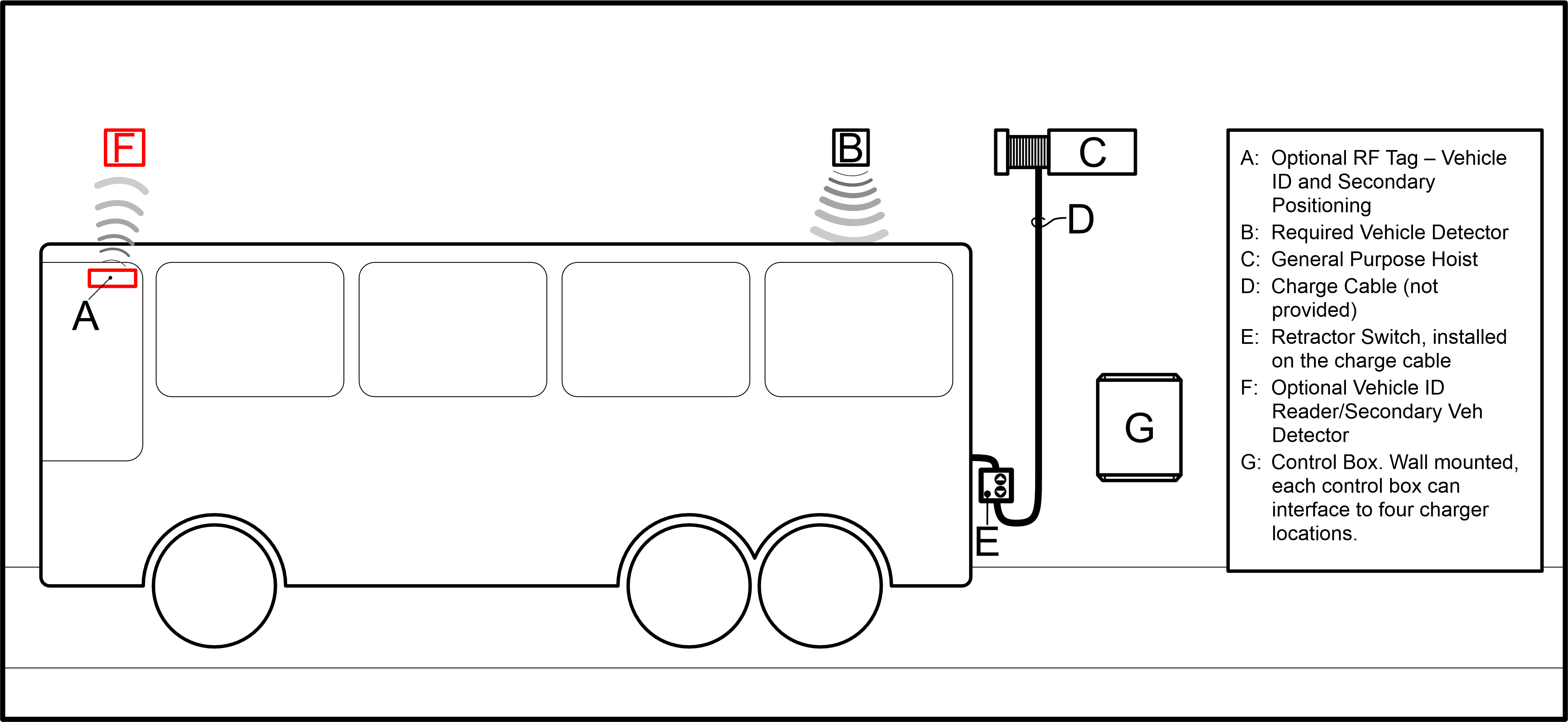
FLEETWATCH Cord Management Systems (FCMS) provide Fleet Operators a simple, easy storage and deployment option for managing the overhead cables of their EV chargers. Using precise location systems capable of accurately pinpointing vehicles to within inches, the FCMS automatically detects and identifies vehicles parked in user defined, charge-capable locations (the Charge Squares). The FCMS is capable of fully hands-free operation, or it can require as much human interaction as the end-user desires.
FAULT INDICATORS CAPTURED AND REPORTED
The FLEETWATCH FCMS works in conjunction with the Fleetwatch JX-200/75/555 line of Data Recorders to enhance safety and monitor critical information. If the vehicle parked inside the Charge Square is authorized, the FCMS automatically establishes a link to retrieve maintenance information (i.e., odometers, hour meters, and diagnostic codes), consumables data such as state-of-charge, and verify any safety related settings (for example, ensuring the parking brake is engaged before cable deployment).
Once user-defined parameters are met, the system deploys the charging cable, lowering it from overhead. Cable Deployment can occur automatically or the deployment can be requested, utilizing a switch mounted above the charge receptacle on the vehicle itself. All user parameters must be met before a deployment will occur. Additional (and optional) triggers are available as well, including RF and wall-mounted controls that bypass safety checks and lower the cord on demand. These bypass controls are useful in case of component failure or to perform standard maintenance operations.
An optional Visual Feedback System (VFS) helps the operator properly position the vehicle inside the Charge Square. It also provides feedback in case of failure to meet requirements, such as Parking Brake Not Set. Utilizing the vehicle’s J1939 bus - or through a variety of available cloud service interfaces to the vehicle charger systems - the VFS can monitor State-of-Charge and provide visual feedback indicating vehicles that are charged and ready to return to service.
If the EV charger or vehicle data systems support cable connection monitoring, the FCMS will automatically retract the charge cable when disconnected (after a user defined delay ). This feature assures no cabling is left laying on the ground where it can be damaged by passing vehicles or present a hazard to pedestrian traffic flow. Cables also retract manually, using the bus-mounted, wall-mounted, or cord-mounted switches.